My take on the iconic 6 axis robotic arms
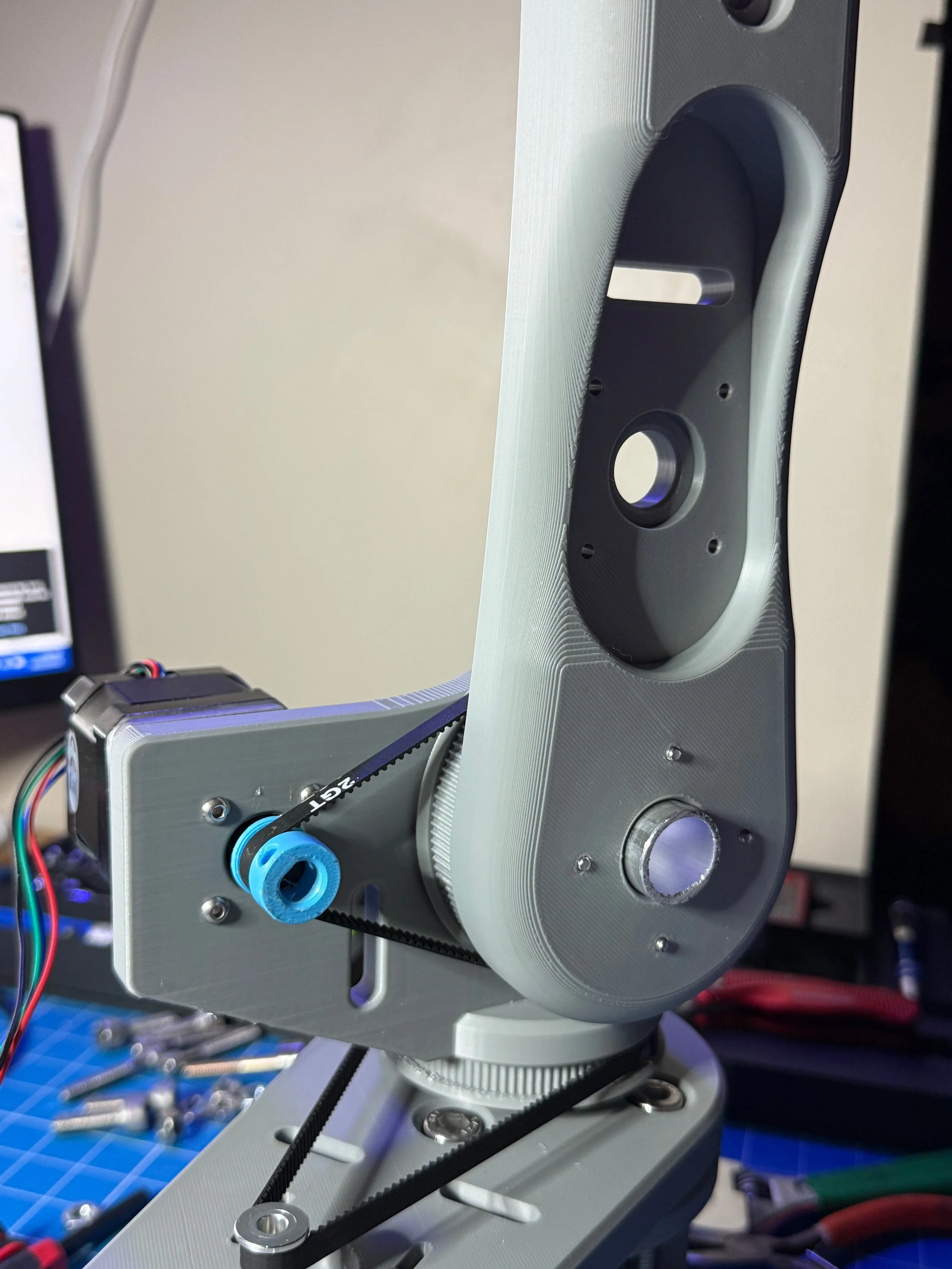
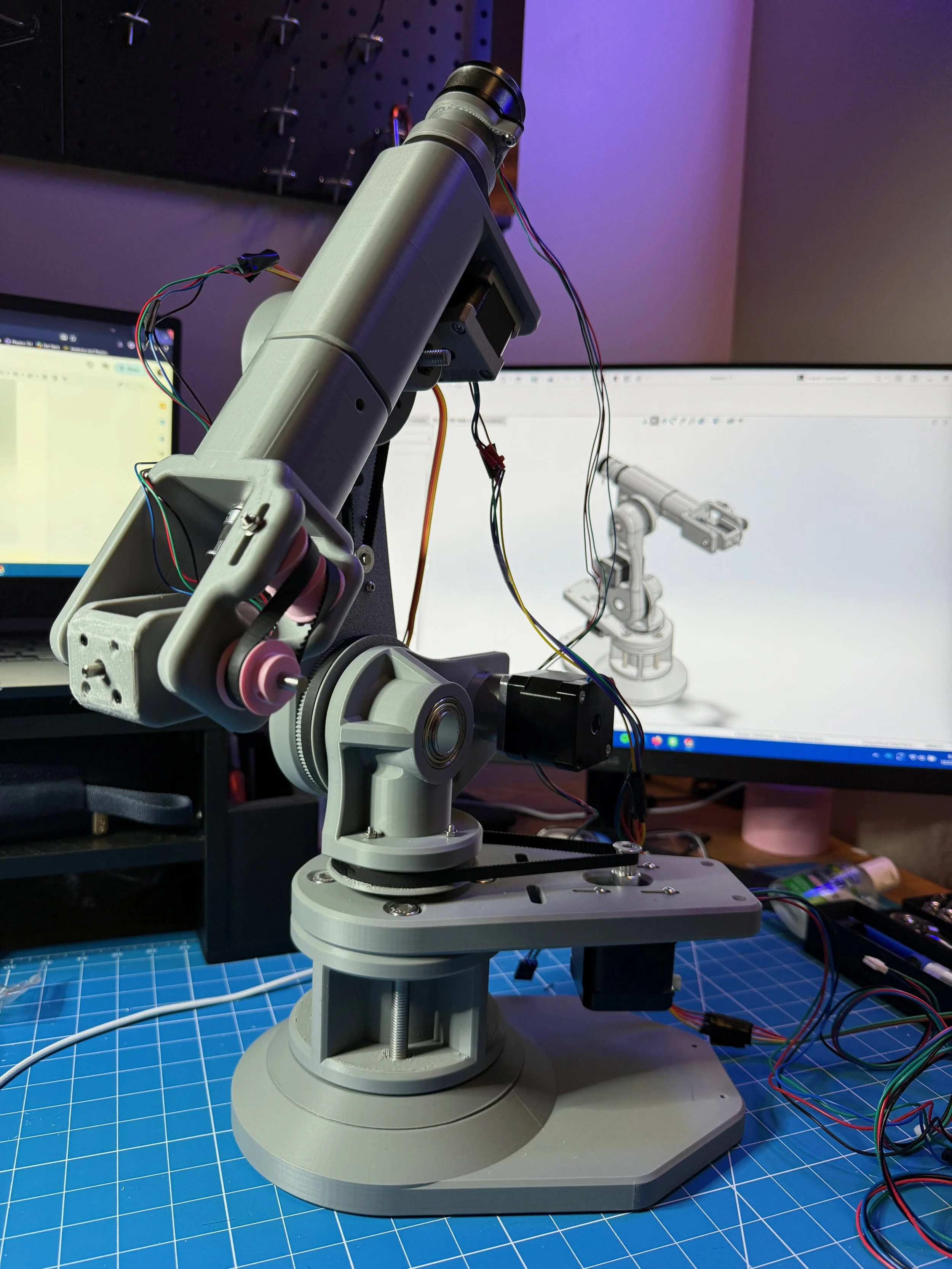
We’ve all seen them, they’re practically in every factory on earth — critical to our development of literally everything. I’ve always had a fixation with robotic arms, so I decided I would design, build, and program my own. Made from stepper motors with reducers and GT2 belts, 3D printed parts, and hardware galore — this arm has a reach of over 30cm and is a more than capable bot.


The Beginning
It started my freshman spring semester — I opened solid works and about 100 tabs of other existing robots — and designed the first model of the robot arm. Over the process of a week, I settled on an aesthetic I liked and a joint configuration based on Kuka arms. I calculated torque necessary for each motor based on the reach I wanted out of the arm, and the payload/weight of the hardware itself. The assembly consisted of 15 unique custom parts, and over 60 parts including hardware, motors, etc.
The Build
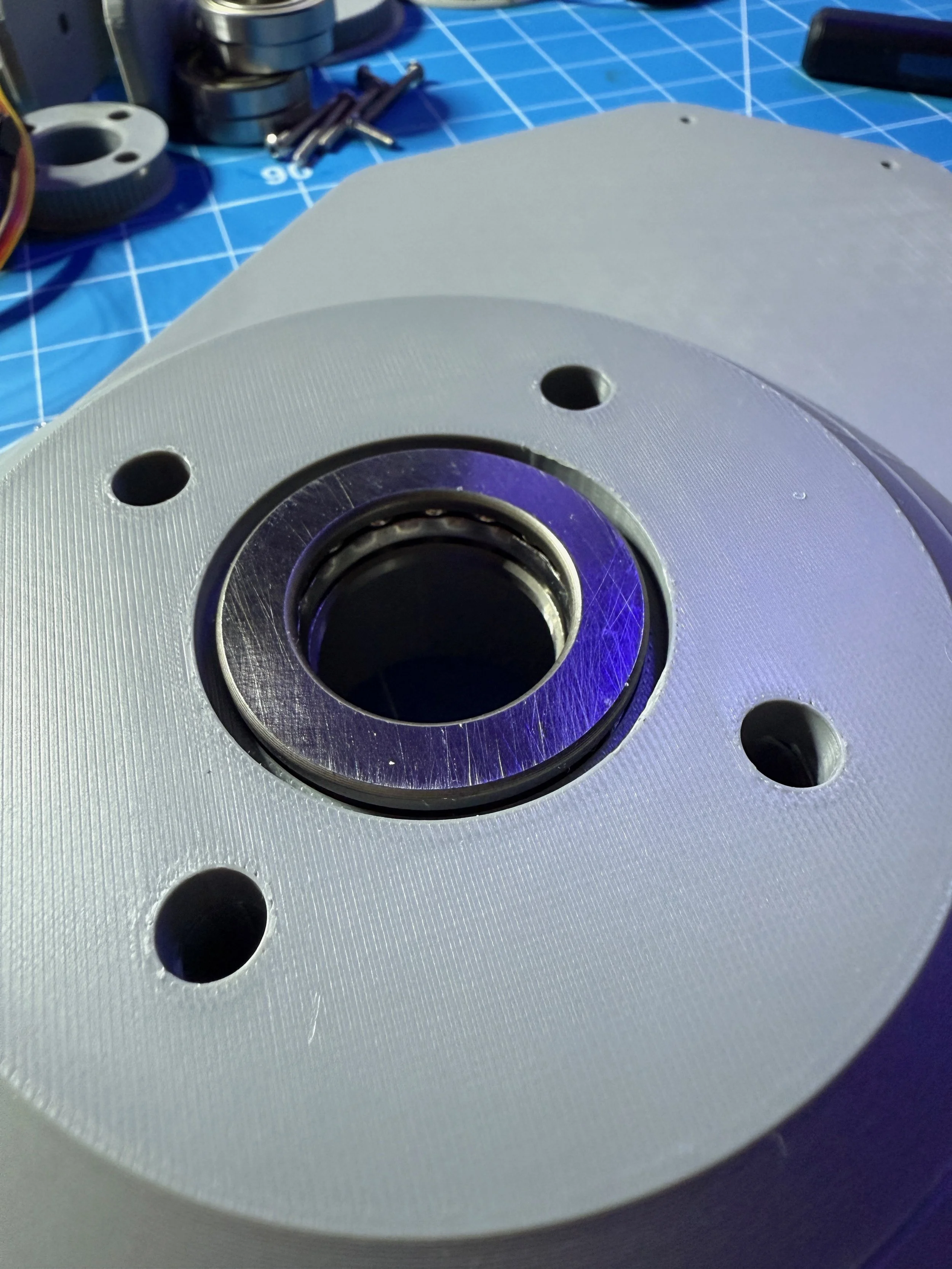
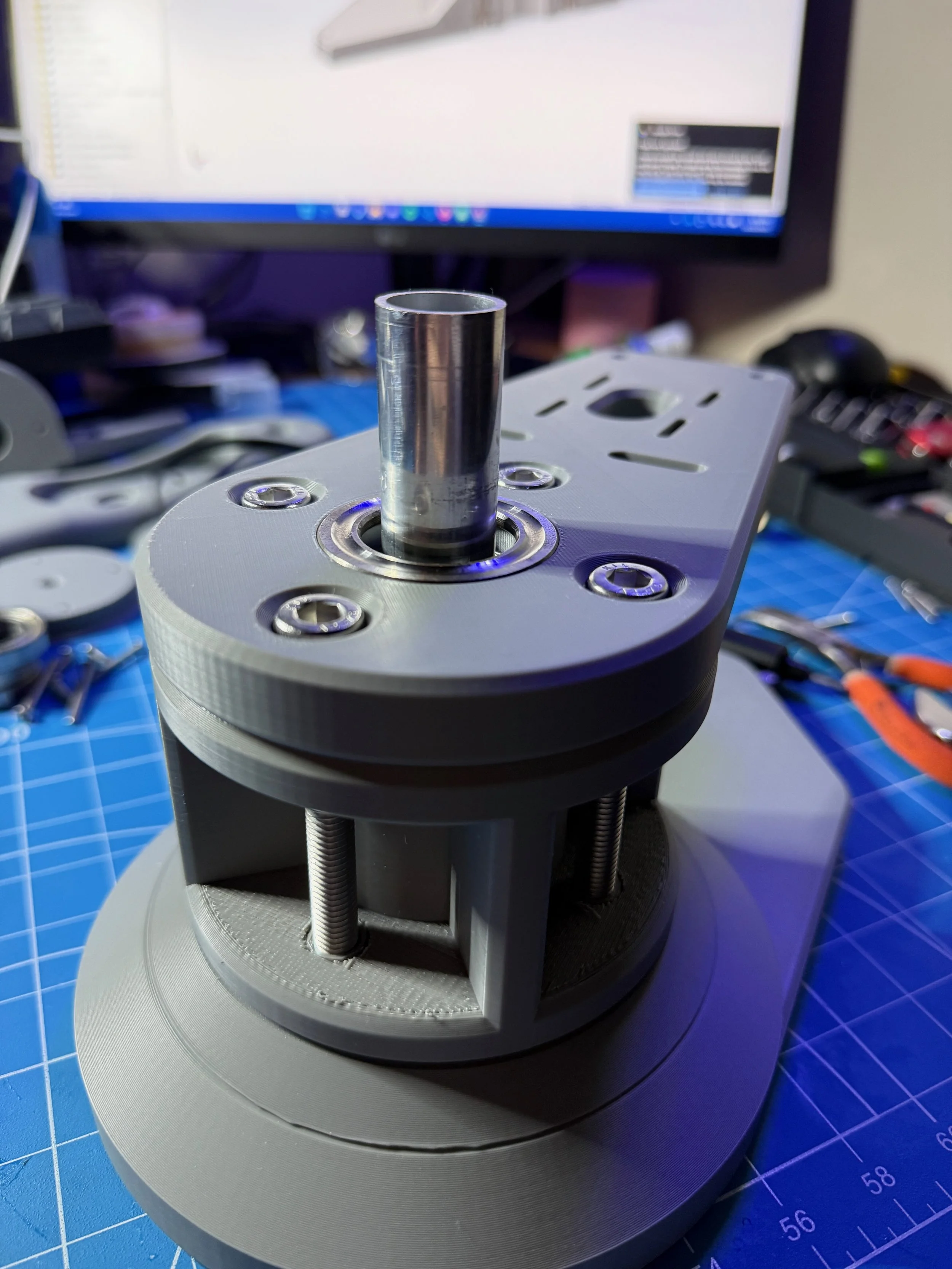
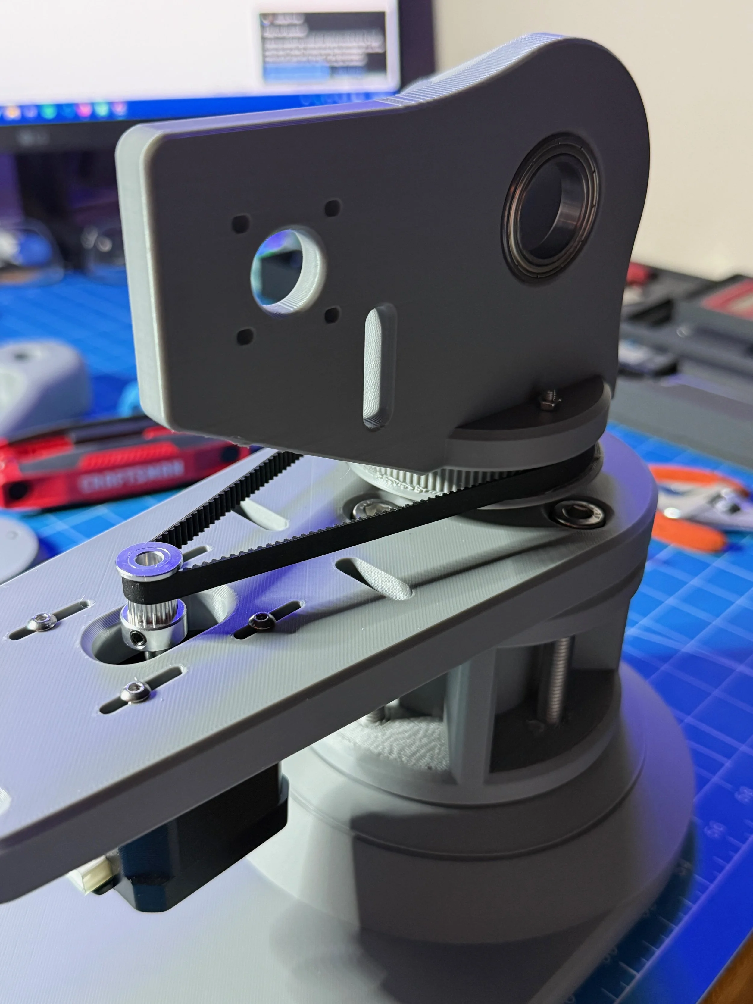
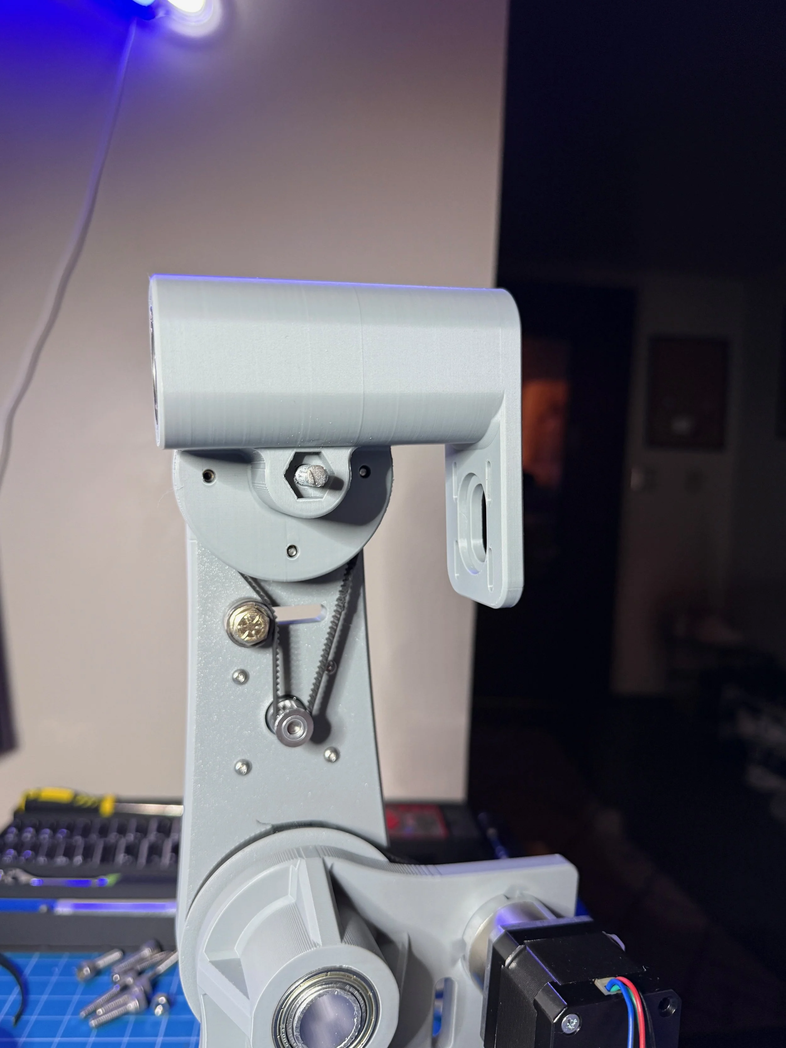
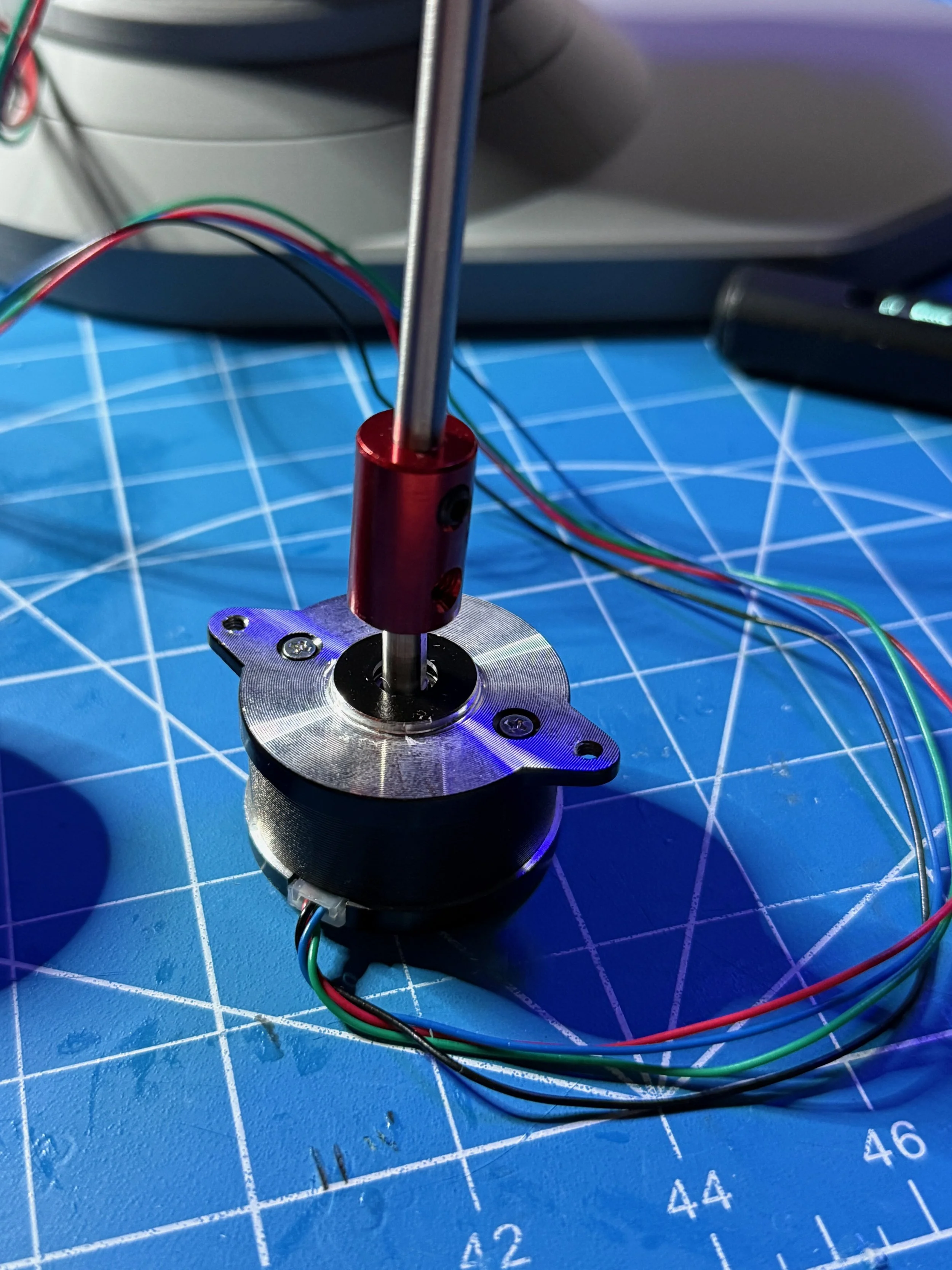
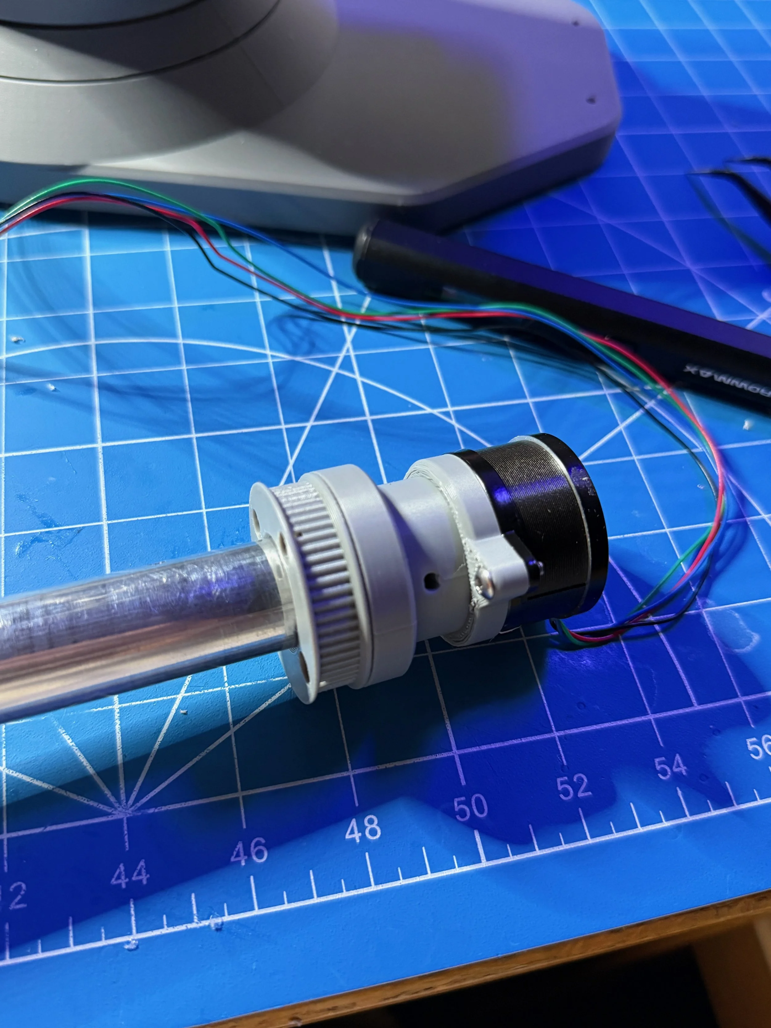
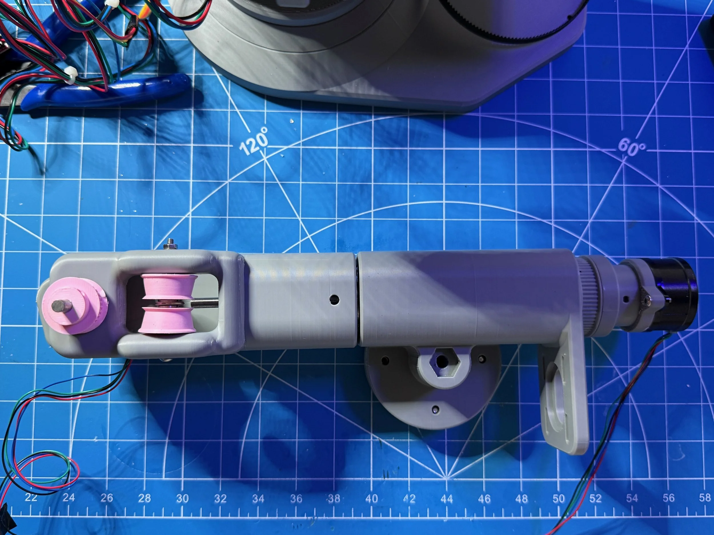
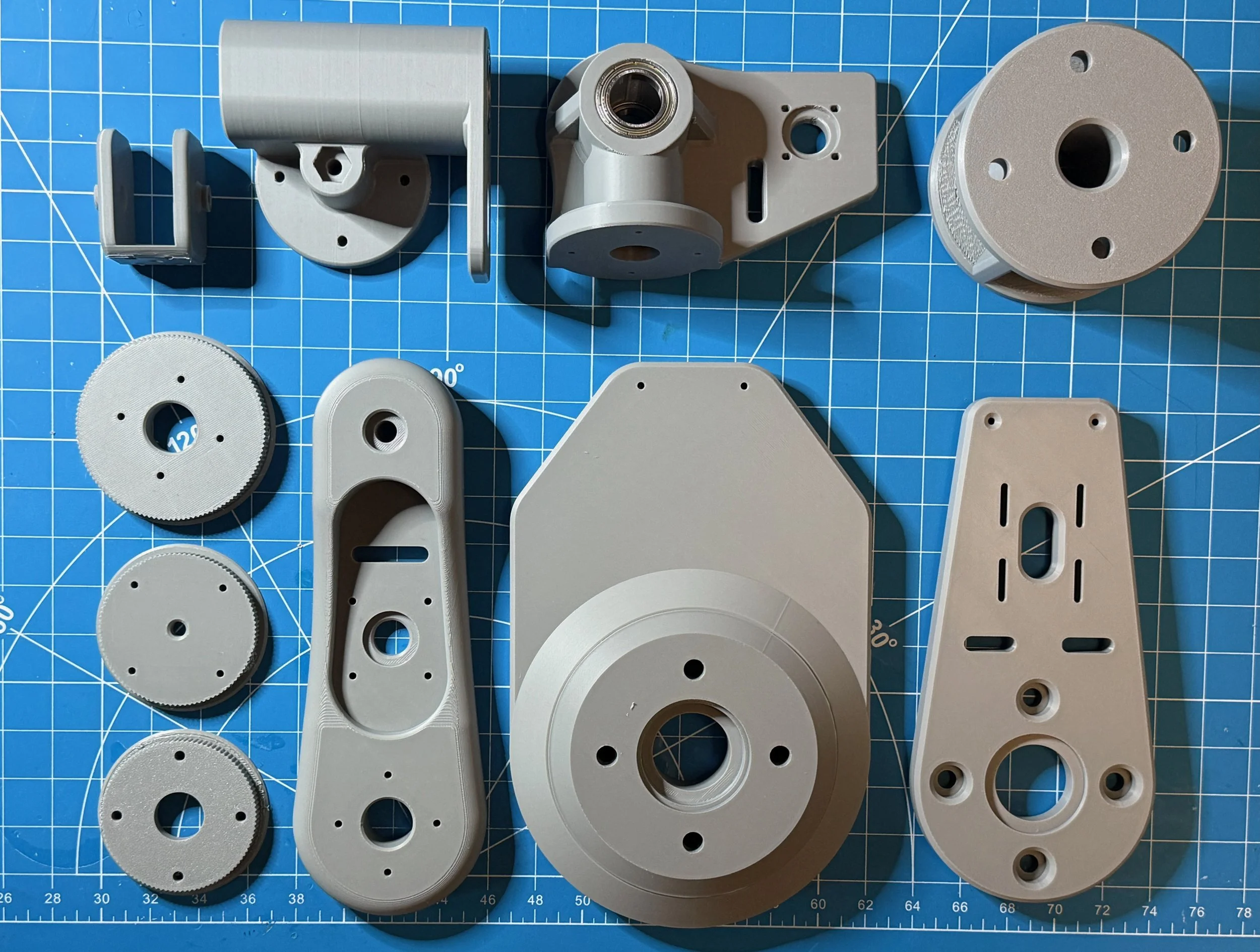
Then began the 3D printing. First, it was low-infill PLA parts quickly made to test fits and the physical assembly process. Of course, nothing goes right the first time, so I went back to CAD to redesign missed tolerances, rethink joint placements, etc. Finally, I reached a point where the bearings snapped in snug, the joints rotated smoothly, and I could put it together in under an hour — these parts were printed in a nice robot gray, most of which are pictured here.

Electronics and Programming
Next is every mechanical engineer’s favorite: circuits and programming. For control of the motors, I chose to use an Arduino MEGA microcontroller board, with a stepper motor driver shield (RAMPS 1.4). This has space for 5 stepper motors, but my robot needs 6… unfortunately I was working on a budget so the most readily available boards at my price point had space for 5 (because they were intended for DIY 3D printers) thus I had to use an external single driver board connected to the Arduino.
On the software side, I developed a firmware for the Arduino that interpreted serial commands via USB connected to a computer. This allowed the software package on the computer to do all the heavy lifting regarding inverse kinematics (gathered from MATLAB) and motor movements. The GUI for controlling the joints is shown here.
The End Result
Currently, the robot is still very much under development. While the main structure is complete, the kinematics and software control needs tuning, and high level task interpretation. My next steps are to:
Design a series of end-effectors, including a gripper
Include path/trajectory planning in software
Integrate with computer vision to recognize objects an carry out tasks
Thanks for following along, more photos of development can be found below!